Introduction:
Spanning Tree Protocol (STP) is a fundamental aspect of networking, particularly in Ethernet environments, ensuring network reliability and preventing loops. Developed by Dr. Radia Perlman in 1985, STP has become a cornerstone in network design. In this comprehensive guide, we’ll delve into the intricacies of STP, breaking down its operation step by step.
What is Spanning Tree Protocol (STP)?
STP is a protocol used to prevent loops in bridged or switched networks. Loops occur when there are redundant paths between switches, leading to broadcast storms and degraded network performance. STP mitigates this risk by dynamically electing a loop-free logical topology among interconnected switches.
Step 1: Bridge Protocol Data Units (BPDU) Exchange
STP operation begins with switches exchanging Bridge Protocol Data Units (BPDUs) to establish a root bridge, the central point of STP topology. BPDUs contain information about bridge ID, path cost, and sender’s identity. Through BPDU exchange, switches determine the root bridge and their own position in the spanning tree.
Step 2: Root Bridge Election
Once BPDUs are exchanged, switches compare received BPDU information to determine the root bridge. The bridge with the lowest Bridge ID (combination of priority and MAC address) becomes the root bridge. Root bridge election ensures a centralized reference point for the spanning tree.
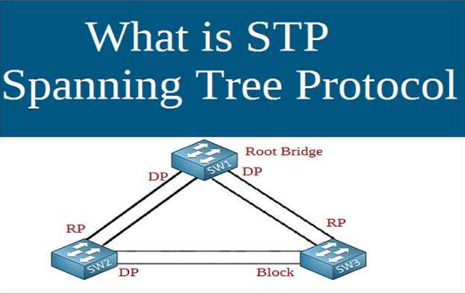
Step 3: Designated and Non-Designated Ports
After electing the root bridge, switches designate ports as either designated or non-designated based on their path to the root bridge. Designated ports are chosen for each segment, providing the shortest path to the root bridge. Non-designated ports are placed in a blocking state to prevent loops.
Step 4: Port Roles: Root, Designated, and Blocked
Each port on a switch assumes one of three roles: root port, designated port, or blocked port. The root port is the port with the lowest path cost to the root bridge. Designated ports are selected per segment to forward traffic toward the root bridge. Blocked ports are set into a blocking state to prevent loops.
Step 5: Topology Changes and Recalculation
STP dynamically adjusts to network changes, such as link failures or additions. Upon detecting a topology change, switches recalculate the spanning tree, potentially altering port roles and states to maintain loop-free operation. This adaptive nature ensures network resilience and stability.
Step 6: Rapid Spanning Tree Protocol (RSTP)
While traditional STP convergence can take several seconds, Rapid Spanning Tree Protocol (RSTP) enhances this process, reducing convergence times to milliseconds. RSTP achieves faster convergence through mechanisms like port roles and states simplification and proposal-agreement process, making it ideal for modern, high-speed networks.
Step 7: Multiple Spanning Tree Protocol (MSTP)
In complex networks with multiple VLANs, Multiple Spanning Tree Protocol (MSTP) provides flexibility by mapping multiple VLANs to a single spanning tree instance. MSTP reduces the overhead associated with maintaining separate spanning trees for each VLAN, optimizing network resources and scalability.
Conclusion:
Spanning Tree Protocol (STP) is a foundational protocol in network design, ensuring loop-free operation and network stability. By following the step-by-step process of STP operation, from BPDU exchange to port role assignment, network administrators can build robust and resilient Ethernet networks. Additionally, advancements like Rapid Spanning Tree Protocol (RSTP) and Multiple Spanning Tree Protocol (MSTP) offer enhanced performance and scalability, catering to the evolving needs of modern networking environments. Understanding STP is crucial for network engineers to effectively design and manage Ethernet networks, ensuring reliable connectivity and optimal performance.
for more articles click